Some would say yes – this is old news; others love the Bavarian company with passion equalling that of a rugby fan. Me, I sit somewhere in the middle. I often wonder though, are we seeing an increase in complexity and electronic control as a means to an end? Or is it an engineer thumbing his nose at the opposition saying, “Look at what we can do!” In reality, it’s a little from column A, and a little from column B.
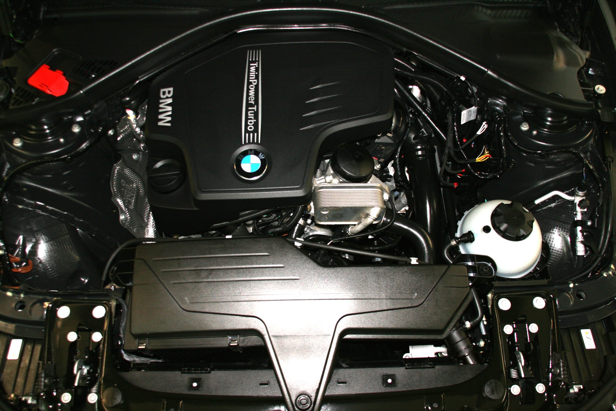
I’m referring to the ever-popular N20 powerplant seen across a range of vehicles in BMW’s line-up.
This little 2.0 litre is punching way above its weight producing a staggering 240HP at 5000rpms – putting many larger capacity engines to shame. Whatever happened to the old saying “you cant beat cubic capacity” ?
The one of the reasons I want to talk about the N20 engine, is its use of oil pump map control and thermal management, and in particular the oil pressure switch.
I know what you are thinking but bear with me – you haven’t wasted your coffee break.
I said oil pressure switch, but what I should have said was “smart sensor” as these components don’t just open a simple circuit when oil pressure lifts the ball from its seat. BMW has been very clever with these units combining multiple information packets into this unassuming pressure transducer.
Oil pressure data is sent to the engine control module via the signal output terminal from the sensor. This data is vital for the engine management system as it needs to select which “oil pressure map” is used during differing operating conditions. Oil temperature is used for thermal management – alongside electronic thermostats, thermos fans and electric water pumps. This is not overly new technology. What is new though, is the oil temperature is taken from the oil gallery by the pressure sensor and transmitted on the same wire that oil pressure is. What kind of Voodoo magic is this?
The answer is of course, signal output using pulse width modulation (PWM) with the signal output from the sensor divided into 3 sections:
- Synchronisation and diagnosis.
- Temperature data
- Pressure Data
The sensor will output a duty cycle of 25% if all is OK. A value of 37.5% means the pressure measurement has failed, and a duty cycle command of 50% means the temperature data is incorrect. Hardware faults within the sensor are reported with a 62.5% duty cycle signal.
What does this mean for the technician tasked with diagnosing faults in this area? Well quite simply with a quality scan tool or oscilloscope, and some knowledge around why the DTC was set, solving and then repairing the problem should be a lot easier.
Technology for technology’s sake? Perhaps not. But I cant wait to see what those crazy engineers come up with next.
Image credits: HLW, CC BY-SA 3.0 https://creativecommons.org/licenses/by-sa/3.0, via Wikimedia Commons